SHIP ТО SHIP TRANSFER GUIDE (PETROLEUM)
(Third Edition 1997)
For Use with Crude
Oil and Petroleum Products
Chapter 9
Equipment
9.1 FENDERS
9.1.1 Fenders
used in STS transfer operations offshore are divided into two categories:
• primary fenders which are positioned along the parallel body of the ship to afford the maximum possible protection while alongside; or
• secondary fenders which may be used to protect bow and stem plating from inadvertent contact during mooring and unmooring.
Primary fenders may be foam filled or of the high
pressure pneumatic type (0.5 to 0.8 Kg/cm2).
Secondary fenders may be either air or foam filled. It can, however, be advantageous for secondary fenders
to be light in weight as they must often be hauled well above the waterline and
located in positions with limited access to lifting gear or support points. It may help if fenders can be moved quickly to counter
possible inadvertent contact.
9.1.2 In most
cases it is probable that tendering operations will be carried out with the
assistance of an STS agency. Such companies usually have service craft available
and these vessels will normally assist in positioning fenders on the relevant
ship.
Fenders may be secured in place on either ship,
however, it is preferable for safety reasons that fenders be secured to the manoeuvring ship. Landing on an unprotected hull section is less likely
if the fenders are rigged on the manoeuvring ship.
When fenders are fitted to the manoeuvring
ship, primary fenders should be positioned one at each end of the parallel
body, with similar additional units fitted in between. The fender string may be made up to a pre-arranged
length. Alternatively in some operations, where four fenders
are used it has been found beneficial to position them in two groups of two. In this way, and with each group positioned well
forward or well aft on the parallel body, better protection can be provided. Secondary fenders may be positioned fore and aft of
the parallel body.
The length of the fender string should be such that
the fenders will be able to distribute the maximum anticipated impact load
within the parallel body of both ships.
Table 9.1 is
included to provide a quick reference guide to fender selection and is only
intended to be used to provide an indication of suitability under the
conditions specified. It should be understood that different approach
velocities would give very different energy absorption requirements.
The table should be entered assuming that both vessels
are of the same tonnage (C tonnes) which is
determined from the following formula:
|
C = |
2 x
Displacement Ship A x Displacement Ship B |
|
Displacement Ship A +
Displacement Ship B |
TABLE 9.1 QUICK
REFERENCE GUIDE FOR FENDER SELECTION
|
C Displacement |
Relative Velocity |
Berthing Energy |
Suggested Fender Quantity |
Typical Pneumatic Fender |
|
Tons |
M/Sec |
Ton Mt |
- |
Metres |
|
1,000 |
0.30 |
002.4 |
3 or more |
1.0x2.0 |
|
3,000 |
0.30 |
007.0 |
« |
1.5x3.0 |
|
6,000 |
0.30 |
014.0 |
« |
2.5 x 5.5 |
|
10,000 |
0.25 |
017.0 |
« |
2.5 x 5.5 |
|
30,000 |
0.25 |
040.0 |
4 or more |
3.3 x 6.5 |
|
50,000 |
0.20 |
048.0 |
« |
3.3 x 6.5 |
|
100,000 |
0.15 |
054.0 |
« |
3.3 x 6.5 |
|
150,000 |
0.15 |
071.0 |
5 or more |
3.3 x 6.5 |
|
200,000 |
0.15 |
093.0 |
« |
3.3 x 6.5 |
|
330,000 |
0.15 |
155.0 |
4 or more |
4.5 x 9.0 |
|
500,000 |
0.15 |
231.0 |
« |
4.5 x 9.0 |
Table 9.1 above
gives approximate numbers and sizes for typical pneumatic fenders. Foam filled fenders may differ slightly in size and it
is strongly recommended that individual fender manufacturer/STS agencies are
consulted prior to suggesting number and sizes offenders for a particular
operation.
Further information referring to fender selection can
be found in Appendix 3.
9.1.3 Fender Requirements
Some shipowners and STS
agencies will be able to call upon experience when assessing fender
requirements for a particular STS transfer operation. It is advisable, however, to determine the forces
which will be generated between berthing ships to provide information relevant
to the selection process.
References should be made to individual fender
manufacturer’s specifications and this should be addressed in terms of sea and
swell conditions among other factors.
The fenders used should be suitable in terms of energy absorptions and stand-off distance. The compressed diameter of the fenders must always be sufficient to ensure that there can be no contact between ships' structures through rolling during the period alongside. It is recommended that the fender diameter is less than half the freeboard of the vessel to prevent inadvertent boarding of the vessel by a fender during inclement weather. It should be noted that as it is not always possible to accurately judge approach speed when berthing, it may be prudent to err on the conservative side when selecting fenders. Manufacturers' recommendations for a calm weather situation and a maximum approach speed of e.g. 0.15 m/sec may be inadequate should weather be a factor and approach speed be significantly higher than planned.
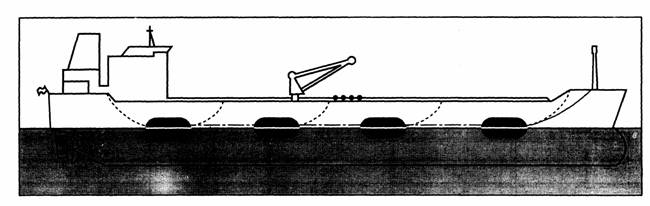
FIGURE 9.1:
FENDERS RIGGED IN A CONTINUOUS STRING
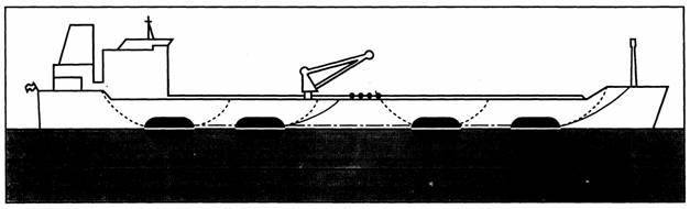
FIGURE 9.2:
FENDERS RIGGED IN PAIRS
9.2 HOSES
9.2.1 Hose Standards
The hoses used for crude oils or petroleum products
should be specially designed and constructed for the product being handled.
9.2.2 Hoses
Size and Length
The diameter of a chosen cargo transfer hose is
governed mainly by the required transfer rate and some detail on this subject
is given in Section 9.2.6. Hoses in
excess of 12- inches in diameter will be
progressively more difficult to handle and particular care will be needed to
avoid damage from kinking.
Hose lengths should be adequate to allow for
differences in cargo manifold height, fore and aft alignment and other
differential movements throughout cargo transfer. Generally, total hose length
(consisting of 3 sections of hose) is
between 75 and 90 feet.
For guidance, a rule of thumb for calculating the minimum bending radius (MBR) of a rubber hose is given in this formula:
MBR = Nominal Bore of Hose in inches x 6
(For example a hose of 12 inches nominal bore will give a minimum bending radius of approximately 72 inches.
9.2.3 Hose Connection
STS transfer operations require hose connections to be
well made. Flanges or quick-release couplings if used should be
in good condition and properly secured to ensure leak-tight connections. The gaskets used at the ship's manifolds and between
each hose should be made from a material suitable for the cargo to be
transferred.
Both ships will be expected to provide the necessary
personnel to connect the hoses.
To simplify hose connection, it is recommended that
ships be fitted with cargo manifolds designed in accordance with OCIMF Recommendations
for Oil Tanker Manifolds and Associated Equipment, with regard to flange
sizes, manifold strength, hose support arrangements, lifting gear, etc.
Adequate provision should be made to support hoses to
prevent excessive strain on manifold fittings.
9.2.4 Hose Inspection and Testing
Hoses used should be subject to regular inspection for
damage or deterioration. A record of inspection and pressure/vacuum testing
where relevant should be available.
Periodic testing of hoses should be in accordance with
the requirements of the specification to which the hose was manufactured and/or
as detailed in the OCIMF publication, Guidelines for the Handling, Storage,
Inspection and Testing of Hoses in the Field.
9.2.5 Marking
Each length of hose should be marked by the
manufacturers with:
• the manufacturer's name or trademark;
• identification of the standard specification for manufacture;
• maximum allowable working pressure;
• month and year of manufacture;
• manufacturer's serial number;
• indication that the hose is electrically continuous or electrically discontinuous, semi-discontinuous or anti-static; and
• the words «0il Service».
9.2.6 Flow Velocities
The maximum permissible flow velocity through a hose
is limited by the construction of the hose. The hose manufacturer's recommendations and
certification should give details. Operators should however take other factors into
account when deciding flow velocities.
- These should include, but not be limited to, the following:
- the factor of safety being applied;
- any limitations imposed by flow velocities in the ship's fixed
piping system;
- weather conditions causing movement of the hose;
- age and condition of the hose;
- amount of use and method of storing the hose; and
-
other local considerations.
Tables
9.2 (a), (b) and (c) are indicative of low rates for hoses supplied
under the British standard.
TABLE 9.2(a) THROUGHPUT v. INSIDE DIAMETER AT VELOCITY = 12 M/S.
|
Velocity 12 Metres/Second |
|||
|
Nominal Inside Diameter of Hose |
Throughput |
||
|
Inches |
Millimetres |
Cubic Metres Per Hour |
Barrels Per Hour |
|
6 8 10 12 16 20 |
152 203 254 305 406 508 |
788 1,400 2,180 3,150 5,600 8,750 |
4,950 8,810 13,700 19,800 35,200 55,000 |
TABLE 9.2(b) THROUGHPUT v. INSIDE DIAMETER AT VELOCITY = 15 M/S.
|
Velocity 15 Metres/Second |
|||
|
Nominal Inside Diameter of Hose |
Throughput |
||
|
Inches |
Millimetres |
Cubic Metres Per Hour |
Barrels Per Hour |
|
6 8 10 12 16 20 |
152 203 254 305 406 508 |
985 1,750 2.730 3,940 7,000 10,900 |
6,190 11,000 17,200 14,700 44,000 68,000 |
TABLE 9.2(c) THROUGHPUT v. INSIDE DIAMETER AT VELOCITY = 21 M/S.
|
Velocity 21 Metres/Second |
|||
|
Nominal Inside Diameter of Hose |
Throughput |
||
|
Inches |
Millimetres |
Cubic Metres Per Hour |
Barrels Per Hour |
|
6 8 10 12 16 20 |
152 203 254 305 406 508 |
1,370 2,450 3,830 5,520 9,780 15,315 |
8,600 15,400 24,000 34,500 61,500 96,300 |
Flow rates for different hose velocity ranges can be
calculated using the following formula:
0.785 x D2 x V x 3600 = cubic metres per hour
Where D
is internal diameter in metres and V is velocity in metres per second.
9.3 MOORING EQUIPMENT
It is recommended that all fairleads used during STS
transfer operations are of an enclosed type which will remain effective for
controlling mooring line leads as the freeboard difference between the two
ships changes. Such fairleads should be strong enough to take the
anticipated mooring loads and large enough to allow the mooring line (plus any
soft rope tail and shackle) to pass through comfortably.
Effective leads between fairleads and mooring bitts
and mooring winches should be available for the handling of all mooring lines.
Appropriate fairleads should be fitted to each ship in
order to accommodate a mooring pattern similar to that shown in Figure 6.2. Apart from the need for headlines and sternlines some special needs for springlines
must be considered. It has been found that full strength enclosed fairleads
and bitts for springlines need to be positioned no
more than 35 metres
forward and aft of the cargo manifold.
It is recommended that all tankers be fitted with an
array of mooring bitts of sufficient strength on each side of the ship. A set of bitts should be positioned between each
enclosed fairlead and its attendant winch in order to accommodate an acceptable
mooring arrangement such as that illustrated. In addition it is recommended that provision be made
for securing fender lines.
9.4 GANGWAY
In general it is recommended that the transfer of
personnel between ships be kept to an absolute minimum and much can often be
accomplished by transferring paperwork by heaving line. When transferring personnel from one
ship to the other, a lightweight insulated gangway, complete with safety net
should be made available by either ship to provide safe access between ships. The use of open-rung ladders is strongly discouraged. If available transfer of personnel may
be carried out by use of an approved workboat.
9.5 LIGHTING
During STS transfers at night, normal in-port deck
lighting will be adequate. Portable spotlights, which should be flameproof, and
bridge wing spotlights are useful for night mooring
and unmooring operations.
9.6 REPRESENTATIVE LIST OF EQUIPMENT
Table 9.3
outlines the equipment which might be available for an STS transfer operation. The table has been prepared as an example and is not
intended to be fully comprehensive.
It should be noted that various STS agencies or shipping company «in house» lightening operations may supply different equipment, including supplementary mooring equipment, fender spacing lines, quick release hooks, portable radios, etc., and therefore it is not possible or desirable to provide a comprehensive list of equipment as each case should be considered individually.
Equipment should be suitably sized for the planned
operation bearing in mind the size of ships, the location and the exposure to
climatic conditions.
TABLE 9.3 REPRESENTATIVE
LIST OF EQUIPMENT
|
No. |
Item |
Notes |
|
4 |
Fenders (primary) |
high pressure pneumatic or foam |
|
4 |
Pennants for towing primary fenders |
with hard eye at one end, plus shackles for securing
to fender |
|
4 |
Tail lines for primary fenders |
with hard eye at one end, plus shackles for securing
to fender |
|
2 |
Fenders (secondary) |
lightweight, pneumatic or foam filled, fitted with
synthetic rope pennants |
|
6 |
Cargo hoses |
usually 2
strings of 3 hose lengths, each string
between 75-90 feet long |
|
2 |
Hose and spool pieces |
fitted with vacuum breaker |
|
8 |
Hose straps |
for lifting and support |