Pro/MECHANICA Online Books
Использование в Pro/ENGINEER
Использование Structure в Pro/ENGINEER
Определение анализа
This section discusses three major types of analyses-static, modal, and thermal-and how to define them. Following is a summary of the three main analysis types:
-
Static - Pro/MECHANICA calculates deformations, stresses, and strains on your model in response to specified loads and subject to specified constraints. Pro/MECHANICA also automatically calculates all measures valid for a static analysis.
-
Modal - Pro/MECHANICA calculates the natural frequencies and mode shapes of your model. Pro/MECHANICA also automatically calculates all measures valid for a modal analysis.
-
Thermal - Pro/MECHANICA calculates thermal response to specified heat loads as the model is subjected to specified prescribed temperatures and/or convection conditions.
Pro/MECHANICA also enables you to define buckling analyses, prestress analyses, contact analyses, and vibration analyses.
When you run design studies, you have the option of running an analysis type called regeneration analysis. This type of analysis simply regenerates your model and is a means of running a design study without first having to run another type of analysis.
Using the Analyses Data Form
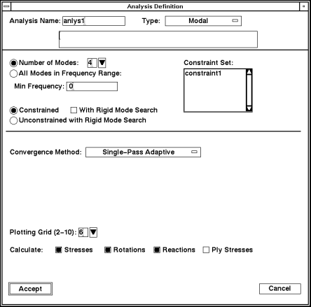
You use the Analysis Definition data form to define conditions for your analysis. If you have already defined at least one analysis for your model, the Analyses data form appears first:
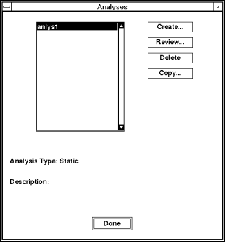
This data form includes the following:
-
Create - Enables you to create a new analysis. When you select this option, the Analysis Definition data form appears. For more information, see the section for the type of analysis you want to define.
-
Review - Enables you to review or edit the analysis you select. The Analysis Definition data form appears containing the values you entered for the selected analysis.
-
Delete - Enables you to delete the currently selected analysis. In Structure, you cannot delete a modal analysis associated with a dynamic analysis.
-
Copy - Enables you to copy the analysis you select from the list. The Copy Analysis data form appears, displaying the name of the selected analysis. Enter a name for the copy and select Accept. Pro/MECHANICA adds the new name to the list.
Defining a Static Analysis
A static analysis calculates deformations, stresses, and strains on your model in response to specified constraints. A static analysis gives you certain information about your model. For example, a static analysis tells you if the material in your model will stand stress and if the part will break (stress analysis), where the part will break (strain analysis), and how much the shape of the model changes (deformation analysis).
Pro/MECHANICA automatically calculates all measures valid for a static analysis.
Review the following guidelines before defining your static analysis:
-
You must select one constraint set and one or more load sets to include in your analysis.
-
If you do not select at least one load set, you may select a constraint set that includes an enforced displacement.
Keep the following points in mind when specifying loads and constraint sets for static analyses:
-
If you delete a constraint or load set that you included in an analysis, you also delete that set from the analysis.
-
Even if you create a new set with the same name as the set you deleted, you must edit the analysis and reselect the set. Otherwise, you may invalidate the analysis and any design studies in which you included the analysis.
-
Pro/MECHANICA calculates results separately for each load set you include in the analysis.
How to Use the Analysis Definition Data Form
To define a static analysis, complete these steps:
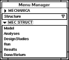
1. From the MECHANICA menu, select Structure > Analyses.

If this is the first analysis you are defining for the model, Pro/MECHANICA displays the following data form:
Note:
If this is not the first analysis you are defining, the software displays the Analyses data form instead. Select Create from the Analyses data form, and Pro/MECHANICA displays the data form shown above.
For models that have temperature-dependent material properties, a Page Down button appears on the Analysis Definition data form. When you select the Page Down button, Pro/MECHANICA displays a second page.
2. Use the Analysis Name and Type fields to identify the analysis and select the analysis type.
3. Select a constraint set from the Constraint Set list and one or more load sets from the Load Sets list.
Note:
If your constraint set includes an enforced displacement constraint, you do not need to select a load set.
4. Use the Convergence Method option menu to select the convergence method you want Pro/MECHANICA to use when running your analysis. Depending on the convergence method, you may need to select or specify additional items on the data form.
5. Customize your results by selecting Stresses, Rotations, Reactions, and Ply Stresses as desired. Also, use the Plotting Grid entry box to specify the level of detail you want Pro/MECHANICA to use when reporting your results.
6. Select Accept to accept the data form. Pro/MECHANICA displays the Analyses data form. Use this data form to create more analyses as well as to review, copy, or delete analyses.
7. Select Done to dismiss the Analyses data form.
Identifying the Analysis
You tell Pro/MECHANICA what type of analysis you want to define and give that analysis a name.
Enter a name in the Analysis Name field.
Click on the option menu in the Type field and select Static as the analysis type. When you select Static, the description field appears. You have the option of entering a description for the analysis.
Selecting Constraint and Load Sets
You must specify one constraint set and one or more load sets to include in the analysis. To do so, use your mouse to select the appropriate constraint set and load set.
You should specify all constraints created for your model that you want included in your analysis. During an analysis, Pro/MECHANICA calculates your model based on these constraints. There is no limit to the number of constraints you can include in a constraint set. However, you can include only one constraint set in a static analysis.
Setting Convergence
Convergence gives you an idea of how accurate your results are. If your analysis did not reach convergence during a design study, the results may not have the desired accuracy. In this case, you need to change something about your model.
Select the convergence method you want Pro/MECHANICA to use when it runs your analysis. You can choose from three methods:
-
Quick Check - Pro/MECHANICA performs a single-pass analysis with uniform polynomial order (p-order) of p=3. You can use this method to verify that you have set up your analysis correctly and to check for gross problems in your model.
-
Single-Pass Adaptive - Pro/MECHANICA runs a first pass at p=3 and determines a local estimate of stress error. Using this error estimate, Pro/MECHANICA determines a new p-order distribution and performs a final pass.
-
If you use the iterative solver, Pro/MECHANICA runs a first pass using the block solver at p=2, followed by a second pass (p=3) using the iterative solver. Using the stress error estimate from pass 2, Pro/MECHANICA performs a third and final pass.
-
See
for more information on using the iterative solver.
-
Multi-Pass Adaptive - When you run a design study, the Structure engine performs calculations and increases the p-order for each element edge until the convergence criteria are satisfied. An analysis converges when the difference in the results of the current pass and the previous pass is within the percentage you specify under Convergence.
Customizing Your Results Output
You can choose from additional options on the Analysis Definition data form to customize your results. You can leave these options set at the default or change them to customize your results.
-
Stresses - Directs Pro/MECHANICA to calculate stresses. If you do not need stress results, especially for a static analysis, you can save disk space by deselecting this item. This option is on by default.
-
Rotations - Directs Pro/MECHANICA to calculate the rotation about each WCS axis over the entire model. Pro/MECHANICA never calculates rotations if your model consists of solid elements, even if this item is selected. Rotations are always zero for these element types. This option is on by default.
Note:
You cannot access results for any quantity you deselect. Pro/MECHANICA calculates all stress and rotation measures even if you do not select Stresses and Rotations on the data form. But you cannot access the same results for measures that you can when you select Stresses, Rotations, and Reactions.
-
Reactions - Directs Pro/MECHANICA to calculate the reaction forces and moments present at constrained points and edges. Pro/MECHANICA does not report reaction data at constraints associated with a UCS (User Coordinate System). This option is on by default.
-
Ply Stresses- Directs Pro/MECHANICA to calculate the stress on each ply of a laminate.
-
Plotting Grid - Determines the level of detail Pro/MECHANICA uses to report results of the analysis when you enter a number from 2 to 10. This value determines how often Pro/MECHANICA will subdivide your model.
CASE STUDY:
Defining a Static Analysis
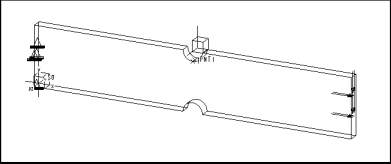
In a prior example, you learned about adding loads and constraints to the notch plate model. Now that these modeling entities are in place you can define analyses for the model. As a refresher, here is what the model looks like:
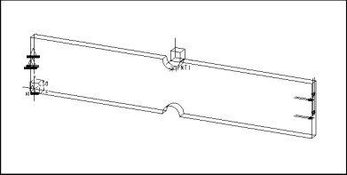
Recall that one of the load and constraint set combinations for this model simulates pure tension. If you want to perform a static analysis of the notch plate as it would behave under these conditions, you might fill in the Analysis Definition data form as follows:
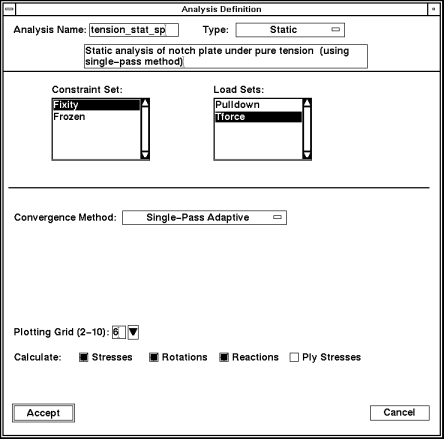
Here is an overview of some of the choices you make when you define the analysis above:
-
Constraint Set - You select Fixity as your constraint set. This constraint set fixes the model in the Trans X direction, while allowing the constrained end of the model to contract appropriately under load.
-
Load Sets - You select Tforce as your load set. This load set applies 10,000 pounds of force in the X direction. This load, together with the Fixity constraint, simulates pure tension.
-
Convergence Method - You select single-pass adaptive as the convergence method. If you want more detailed convergence information, you can run a second analysis using the multi-pass adaptive convergence method later.
-
Plotting Grid - You set this value to 6 to show a finer level of detail in the results.
-
Calculate - You keep the Stress, Rotations, Reactions, and Ply Stresses selections on. These selections offer additional results data for this model.
Defining a Modal Analysis
In a modal analysis, Pro/MECHANICA calculates the natural frequencies and mode shapes of your model. Pro/MECHANICA also automatically calculates all measures valid for a modal analysis.
In a modal analysis, you can see the natural frequencies of your model when subjected to time-dependent and/or oscillatory/vibration loads.
You must run a modal analysis before running any dynamic analysis, such as dynamic vibration or dynamic shock.
Keep the following points in mind when specifying constraint sets for modal analyses:
-
If you include a constraint set in your modal analysis, be aware that deleting the constraint set from the model also deletes the constraint set from the analysis. Even if you create a new set with the same name as the set you deleted, you must edit the analysis and reselect the set. Otherwise, you may invalidate the analysis and any design studies in which you included the analysis.
-
Do not select constraint sets that contain enforced displacement constraints.
How to Use the Analysis Definition Data Form
To define a modal analysis, complete these steps:
1. From the MECHANICA menu, select Structure>Analyses.
If this is the first analysis you are defining for the model, Pro/MECHANICA displays the following data form:
Note:
If this is not the first analysis you are defining, the software displays the Analyses data form instead. Select Create from the Analyses data form, and Pro/MECHANICA displays the data form shown above.
For models that have temperature-dependent material properties, a Page Down button appears on the Analysis Definition data form. When you select the Page Down button, Pro/MECHANICA displays a second page.
2. Use the Analysis Name and Type fields to identify the analysis and select the analysis type.
3. Complete each of the following steps, as applicable:
-
Select the Number of Modes button or All Modes In Frequency Range button.
-
If you selected the Number of Modes button, use the entry box to select the number of modes you want Pro/MECHANICA to use when calculating your analysis.
-
Use the Min Frequency entry box to select a frequency minimum. If you selected the All Modes In Frequency Range button, also enter a maximum frequency in the Max Frequency entry box that appears after you select the button.
-
Select the Constrained button if you want Pro/MECHANICA to use a constraint. Also, use the Constraint Set list to select a constraint set and the With Rigid Mode Search button to indicate whether you want Pro/MECHANICA to search for rigid modes.
-
Select the Unconstrained with Rigid Mode Search button if you do not want to use a constraint for the analysis.
4. Use the Convergence Method option menu to select the convergence method you want Pro/MECHANICA to use when running your analysis. Depending on the convergence method, you may need to select or specify additional items on the data form.
5. Customize your results by selecting Stresses, Rotations, and Reactions, as desired. Also, use the Plotting Grid entry box to specify the level of detail you want Pro/MECHANICA to use when reporting your results.
6. Select Accept to accept the data form. Pro/MECHANICA displays the Analyses data form. Use this data form to create more analyses as well as to review, copy, or delete analyses.
7. Select Done to dismiss the Analyses data form.
Identifying the Analysis
You tell Pro/MECHANICA what type of analysis you want to define and give that analysis a name.
Enter a name in the Analysis Name field. You cannot use the same name for both an analysis and a design study.
Click on the option menu in the Type field and select Modal as the analysis type. When you select Modal, the description field appears. You have the option of entering a description for the analysis.
Selecting Modes and Constraints
This portion of the data form includes two tasks-selecting the number of modes and selecting constraint options.
You specify the options you want Pro/MECHANICA to use when calculating your analysis.
Selecting a Mode Option
You can select a mode option from the following (Number of Modes is the default):
-
Number of Modes - Enter the number of modes above a specified minimum frequency that you want Pro/MECHANICA to take into account when calculating results for this analysis.
-
If you select With Rigid Mode Search, Pro/MECHANICA includes rigid modes in the number of modes it reports after a run. You should therefore add the number of rigid modes to the number of non-rigid modes you want reported, so you get the results for all the modes you want.
-
For example, a model with no constraints has six rigid body modes. If you want four non-rigid modes, you should enter 10 for Number of Modes.
-
Enter a number from 1 to 99. The default is 4.
-
All Modes in Frequency Range - Select this item if you want Pro/MECHANICA to report modes within a range you specify. You specify this range by entering values for the items Min Frequency and Max Frequency.
Selecting a Frequency Option
You can select a frequency option from the following:
-
Min Frequency - Enter a frequency. Pro/MECHANICA reports modes at or above that frequency. The number of modes Pro/MECHANICA reports depends on whether you selected Number of Modes or All Modes in Frequency Range. You must enter a value greater than or equal to 0.
-
Max Frequency - Appears if you selected All Modes in Frequency Range. Enter a frequency. Pro/MECHANICA reports all modes at or below that frequency and above the Min Frequency you specified. You must enter a positive value greater than the Min Frequency.
Selecting a Constraint Option
You can select a constraint option from the following:
-
Constrained - Select this item if you want the analysis to include a constraint. If you select this item, select one constraint set from the list to the right of the item. If you have not defined any constraint sets, this item does not appear.
-
If your model is not fully constrained, you should also select With Rigid Mode Search, located to the right of Constrained. When you select With Rigid Mode Search, Pro/MECHANICA looks for and reports rigid body modes when it runs a design study containing this analysis.
-
If you do not select With Rigid Mode Search and the model is not fully constrained, you will get a fatal error when you try to run a design study containing this analysis. If you are not certain that your model is fully constrained, you should select this item.
-
If you select With Rigid Mode Search and your model is fully constrained, it does not cause any problems in the design study run. However, Pro/MECHANICA makes extra calculations, adding time to the run.
-
Unconstrained with Rigid Mode Search - Select this item if you do not select a constraint set. When you select this item, Pro/MECHANICA looks for and reports rigid body modes when it runs a design study containing this analysis. You should select this option if you want to examine rigid body movement.
Setting Convergence
Convergence gives you an idea of how accurate your results are. If your analysis did not reach convergence during a design study, the results may not have the desired accuracy. In this case, you need to change something about your model.
Select the convergence method you want Pro/MECHANICA to use when it runs your analysis. You can choose from three methods:
-
Quick Check - Pro/MECHANICA performs a single-pass analysis with uniform p=3. You can use this method to verify that you have set up your analysis correctly and to check for gross problems in your model.
-
Single-Pass Adaptive - Pro/MECHANICA runs a first pass at p=3 and determines a local estimate of stress error. Using this error estimate, Pro/MECHANICA determines a new p-order distribution and performs a final pass.
-
If you use the iterative solver, Pro/MECHANICA runs a first pass using the block solver at p=2, followed by a second pass (p=3) using the iterative solver. Using the stress error estimate from pass 2, Pro/MECHANICA performs a third and final pass.
-
See
for more information on using the iterative solver.
-
Multi-Pass Adaptive - When you run a design study, the Structure engine performs calculations and increases the p-order for each element edge until the convergence criteria are satisfied. An analysis converges when the difference in the results of the current pass and the previous pass is within the percentage you specify under Convergence. You would use this method for specialized models.
Customizing Your Results Output
You can choose from additional options on the Analysis Definition data form to customize your results. You can leave these options set at the default or change them to customize your results.
-
Stresses - Directs Pro/MECHANICA to calculate stresses. If you do not need stress results, you can save disk space by deselecting this item. This option is on by default.
-
Rotations - Directs Pro/MECHANICA to calculate the rotation about each WCS axis over the entire model. Pro/MECHANICA never calculates rotations if your model consists only of solid elements, even if this item is selected. Rotations are always zero for these element types. This option is on by default.
-
Reactions - Directs Pro/MECHANICA to calculate the reaction forces and moments present at constrained points and edges. Pro/MECHANICA does not report reaction data at constraints associated with a UCS. This option is on by default.
-
Plotting Grid - Determines the level of detail Pro/MECHANICA uses to report results of the analysis when you enter a number from 2 to 10.
CASE STUDY:
Defining a Modal Analysis
In
addition to defining a static analysis for the notch plate model as described in
Recall that one of the constraint sets for this model fixes the far end of the model in all degrees of freedom-in effect, turning the model into a cantilevered beam. If you want to perform a modal analysis of the notch plate as it would behave if thus constrained, you might fill in the Analysis Definition data form as follows:
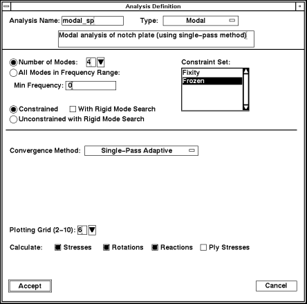
Here is an overview of some of the choices you make when you define the analysis above:
-
Number of Modes - You specify 4 as the number of modes and 0 as the minimum frequency. In doing so, you instruct Pro/MECHANICA to calculate results for the first four nonrigid modes it finds above a frequency of zero. Each mode reports frequency values.
-
Constrained - You select the Constrained option to include the Frozen constraint set displayed in the Constraint Set list box to the right. As mentioned, this constraint set fixes the back end of the notch plate in all six degrees of freedom.
-
Convergence Method - You select single-pass adaptive as the convergence method. If you want more detailed convergence information, you can run a second analysis using the multi-pass adaptive convergence method later.
-
Plotting Grid - You set this value to 6 to show a finer level of detail in the results.
-
Calculate - Calculate the Stress, Rotations, Reactions, and Ply Stresses. These selections offer additional results data for this model.
Defining a Thermal Analysis
You can define two types of thermal analyses: steady-state thermal and transient thermal. Steady-state thermal is described here.
A steady-state thermal analysis calculates a thermal response to specified heat loads subject to specified prescribed temperatures and/or convection conditions. For example, you could define a steady-state thermal analysis for a model with a metal cooling fin, as on a lawn mower engine. Through analysis definition, you would subject the cooling fin to a constant head load (piston heat output) and a forced convection (moving air).
Pro/MECHANICA also automatically calculates all generic, mass property, and thermal measures.
Review the following guidelines before defining your thermal analysis:
-
You must select at least one constraint set for your analysis.
-
You can include any number of load sets, although load sets are not required for a thermal analysis.
Keep the following points in mind when specifying loads and constraint sets for thermal analyses:
-
If you delete a constraint set or load set after you include it in an analysis, you also delete that set from the analysis.
-
If you create a new set with the same name as the set you deleted, you must edit the analysis and reselect the set. Otherwise, you may invalidate the analysis and any design studies in which you included it.
How to Use the Analysis Definition Data Form
To define a thermal analysis, complete these steps:
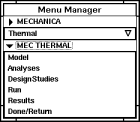
1. From the MECHANICA menu, select Thermal > Analyses.
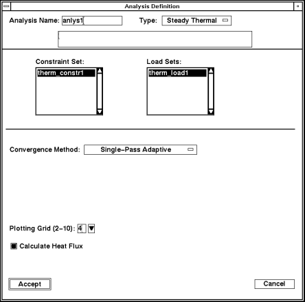
If this is the first analysis you are defining for the model, Pro/MECHANICA displays the following data form:
Note:
If this is not the first analysis you are defining, the software displays the Analyses data form instead. Select Create from the Analyses data form, and Pro/MECHANICA displays the data form shown above.
2. Use the Analysis Name and Type fields to identify the analysis and select the analysis type.
3. Select a constraint set from the Constraint Set list. If you defined heat loads for the model, use the Load Sets list to select one or more load sets as desired.
4. Use the Convergence Method option menu to select the convergence method you want Pro/MECHANICA to use when running your analysis. Depending on the convergence method, you may need to select or specify additional items on the data form.
5. Use the Plotting Grid entry box to specify the level of detail you want Pro/MECHANICA to use when reporting your results. Also, you can optionally select Calculate Heat Flux at this time.
6. Select Accept to accept the data form. Pro/MECHANICA displays the Analyses data form. Use this data form to create more analyses as well as to review, copy, or delete analyses.
7. Select Done to dismiss the Analyses data form.
Identifying the Analysis
You tell Pro/MECHANICA what type of analysis you want to define and give that analysis a name.
Enter a name in the Analysis Name field. You cannot use the same name for both an analysis and a design study.
Click on the option menu in the Type field and select Steady Thermal as the analysis type. When you select Steady Thermal, the description field appears. You have the option of entering a description for the analysis.
Selecting Constraint and Load Sets
Select one constraint set. You can select as many load sets as you wish, although no load sets are required for a thermal analysis.
The constraint set should include all the constraints in your model that you want included in your analysis. During an analysis, Pro/MECHANICA calculates the behavior of your model based on these constraints. There is no limit to the number of constraints you can include in a constraint set. However, you can only include one constraint set in a thermal analysis.
Setting Convergence
Convergence gives you an idea of how accurate your results are. If your analysis did not reach convergence during a design study, the results may not have the desired accuracy. In this case, you may need to change something about your model. Defining convergence for your analysis involves four steps-selecting the method, selecting the quantity, setting the accuracy, and setting the polynomial order:
To learn about these steps, read the following:
Selecting the Method
You tell Pro/MECHANICA which convergence method to use when running your analysis. You can choose from two methods:
-
Quick Check - Pro/MECHANICA performs a single pass analysis with uniform p=3. You can use this method to verify that you have set up your analysis correctly and to check for gross problems in your model.
-
Single-Pass Adaptive - Pro/MECHANICA runs a first pass at p=3 and determines a local estimate of stress error. Using this error estimate, Pro/MECHANICA determines a new p-order distribution and performs a final pass.
-
If you use the iterative solver, Pro/MECHANICA runs a first pass using the block solver at p=2, followed by a second pass (p=3) using the iterative solver. Using the stress error estimate from pass 2, Pro/MECHANICA performs a third and final pass.
-
Multi-Pass Adaptive - When you run a design study, the Structure engine performs calculations and increases the p-order for each element edge until the convergence criteria are satisfied. An analysis converges when the difference in the results of the current pass and the previous pass are within the percentage you specify for Convergence.
Selecting the Quantity
Pro/MECHANICA uses quantities to calculate convergence for your model. You can select one of three options for the convergence quantity:
-
Local Temperatures + Lcl Energy Norms - Pro/MECHANICA calculates convergence of the temperatures along each element edge and of the energy norms in each element.
-
The energy norm of an element is a scalar quantity that is proportional to the integral over the element of the flux squared. It is analogous to element strain energy in a static structural analysis.
-
Local Temperatures + Lcl Energy Norms is the default quantity.
-
Local Temps & Lcl & Glbl Energy Norms - Pro/MECHANICA uses global norms in addition to temperatures and local energy norms to calculate convergence. The global energy norm is the sum of the energy norms of all elements in the model.
-
The global energy norm error measure is a single scalar value proportional to the square root of the estimated error in the global energy norm.
-
Pro/MECHANICA checks convergence for the global energy norm by extrapolating the global norm of three successive calculations. As a result, global norm convergence considers the rate of convergence. This option provides high accuracy but can also mean greater computation time.
-
Measures - Pro/MECHANICA uses one or more measures to determine convergence.
-
Use Measures for convergence if you are interested either in results for one or more specific quantities, such as maximum flux magnitude, or in results at a particular location, such as a boundary condition or local flux concentration.
-
Using Measures ensures that results will converge for the quantities in which you are interested. Using measures may also lower the computation time for your design study.
Setting the Accuracy
You set a convergence accuracy percentage for Pro/MECHANICA to use in calculating your analysis.
Pro/MECHANICA displays a percentage field. You can enter the percentage Pro/MECHANICA uses to determine convergence for this analysis. This option is available for multi-pass adaptive convergence only.
The Structure engine performs calculations at increasingly higher polynomial orders, converging when the difference in the results of the last two calculations is within the percentage you specify here.
The engine finishes calculating results when the analysis converges or when it has reached the maximum polynomial order that you also specify on this data form.
If an analysis does not reach convergence during a design study, you may need to change something in your model to get better results.
Lower convergence percentages yield more accurate results, but Pro/MECHANICA may take longer to reach convergence. You should balance the level of accuracy you need with the amount of time it will take to run a design study containing this analysis.
The default convergence value is 10%. For most analyses, you should enter a value between 1% and 25%. If you enter a convergence value outside this range, Pro/MECHANICA asks you to confirm the value you entered when you select Accept on this data form.
Pro/MECHANICA measures convergence for one or more quantities that you specify.
Setting the Polynomial Order
You can enter minimum and maximum values to determine the polynomial orders Pro/MECHANICA uses when analyzing your model. The available values are from 1 to 9. The default minimum is 1; the default maximum is 6. This option is available for multi-pass convergence only.
The Structure engine begins with all element edges at the minimum polynomial order and repeats its calculations at increasingly higher polynomial orders for each edge until it reaches one of the following values:
-
the maximum polynomial order that you specify here.
-
the convergence percentage. This happens when the results of the last two calculations are within the convergence percentage you specified elsewhere on this data form.
When entering values for the polynomial order, consider the following points:
-
The calculation time at each polynomial order increases significantly over the previous order.
-
A low convergence percentage may require a high polynomial order.
Customizing Your Results Output
You can choose from additional options on the Analysis Definition data form to customize your results. You can leave these options set at the default or change them to customize your results.
-
Calculate Heat Flux - Select this item to direct Pro/MECHANICA to calculate heat flux. This option is on by default.
-
If you do not select Calculate Heat Flux, you cannot access results for heat flux when you look at results for this analysis.
-
Plotting Grid - Enter a number from 2 to 10 to determine the level of detail Pro/MECHANICA uses to report results of the analysis.
-
This value is the number of intervals along each edge or across a face of each element that Pro/MECHANICA uses to create plotting grids. Pro/MECHANICA calculates quantity values at the intersections of grid lines.
-
Pro/MECHANICA reports results for each grid intersection point and interpolates these values to show results elsewhere.
-
If you enter a higher number, the grid will be finer, and Pro/MECHANICA reports values from more locations on each element. At lower numbers, Pro/MECHANICA takes less time to calculate results, and the data requires significantly less space. The default is 4.
Understanding Buckling Analyses
You can use a buckling analysis to calculate the critical load at which a structure will buckle, as well as the model's stresses, strains, and deformations at the onset of buckling.
In a buckling analysis, Pro/MECHANICA calculates a buckling load factor (BLF) and mode shape for each buckling mode you request. The BLF is the magnification factor by which the loads applied in a previously specified static analysis would have to be multiplied to produce the critical buckling load. The constraint set specified in the previous static analysis is also used in the buckling analysis. Pro/MECHANICA automatically calculates all predefined measures valid for a static analysis.
Pro/MECHANICA buckling analysis is a linear eigenvalue bifurcation instability analysis as described in The Finite Element Method, Third Edition, by O.C. Zienkiewicz, pages 513-514. Large displacement or nonlinear buckling investigations may produce significantly different results, depending on the type of model and loads being examined.
Before defining your buckling analysis, you should have defined a static analysis. In the static analysis, Pro/MECHANICA calculates the stress stiffening of your model due to the applied forces. You then define your buckling analysis. Pro/MECHANICA uses the buckling analysis to calculate the model's elastic stiffness-stiffening due to geometry and material properties. Pro/MECHANICA then uses the two solutions to calculate the BLF.
Understanding Prestress Static Analyses
You can use a prestress analysis to simulate how a prestiffened or prestressed structure affects your model's deformations, stresses, and strains.
Before running a prestress static analysis, you must first run a static analysis. Pro/MECHANICA uses the results from your static analysis to calculate the prestress static analysis. In a prestress static analysis, Pro/MECHANICA calculates deformations, stresses, and strains on your model in response to specified loads and subject to specified constraints. Pro/MECHANICA also automatically calculates all measures valid for a static analysis.
You run a prestress static analysis in addition to a static analysis for the following situations:
-
if you want a transverse effect for your model.
-
if you think your applied loads affect the stiffness of the model-for example, if you have a model with an existing load that projects an existing force.
Review the following guidelines before defining your prestress static analysis:
-
You can define a prestress analysis for 3D models only.
-
You must specify one constraint set and one or more load sets. You do not need a load set if you use a constraint set with an enforced displacement.
-
You do not have to select a constraint set if your model is sufficiently constrained by a point constraint. A point constraint is equivalent to a point-to-ground spring with infinite stiffness.
-
If you delete a constraint set or load set after you include it in an analysis, you also delete that set from the analysis.
-
Even if you create a new set with the same name as the set you deleted, you must edit the analysis and reselect the set. Otherwise, you may invalidate the analysis and any design studies in which you include it.
-
You cannot use single-pass adaptive convergence for prestress static analyses.
Pro/MECHANICA enables you to run either a static analysis or a prestress static analysis. In a static analysis, you calculate stresses and strains on your model subject to loads and constraints you assigned. However, you may need more specified information about your model than a static analysis can provide. For example, if the specified loads in the static analysis are close in magnitude to a corresponding buckling load, the pre-stiffening effects are negligible from a static analysis. In this case, you should run a prestress static analysis.
A prestress static analysis determines the strengthening or weakening of the part due to the applied loads. For example, Pro/MECHANICA can determine the strengthening or weakening of an applied load on a ski lift-for example, a pretension cable.
Understanding Prestress Modal Analyses
You can use a prestress modal analysis to determine the natural frequency and mode shapes of your model.
In a prestress modal analysis, Pro/MECHANICA uses results from your previously defined static analysis to calculate the natural frequencies and mode shapes of your model. Pro/MECHANICA also automatically calculates all measures valid for a modal analysis.
Review the following guidelines before defining your prestress modal analysis:
-
If you delete a constraint set or load set after you include it in an analysis, you also delete that set from the analysis.
-
Even if you create a new set with the same name as the set you deleted, you must edit the analysis and reselect the set. Otherwise, you may invalidate the analysis and any design studies in which you include the analysis.
-
Units of modal frequency shown in results are always cycles per unit of time. The units of time are affected by the force/length/time units you used to define the model. Pro/MECHANICA does not report modal frequency in terms of radians per unit of time.
-
You must have a previously-run static analysis. Pro/MECHANICA uses the results of the static analysis to run the prestress modal analysis.
-
You must specify a constraint set unless one of the following applies to your model:
-
You select Unconstrained with Rigid Mode Search when you define the analysis.
-
Your model is sufficiently constrained by a point constraint. A point constraint is equivalent to a point to ground spring with infinite stiffness.
-
In a static analysis, Pro/MECHANICA calculates stresses and strains on your model subject to loads and constraints you assigned. However, you may need more specific information about your model than a static analysis can provide. For example, in rotating machinery, such as a turbine blade, you may want to run a prestress modal analysis after your static analysis to get more detailed information about the applied loads and the stiffening and weakening of those loads.
Understanding Contact Analyses
You can use contact analyses to observe how displacement, stresses, contact pressures, and/or measures affect the contact regions of your model. During a contact analysis, Pro/MECHANICA monitors any changes to the surfaces of your model that are defined as contact regions.
Review the following guidelines before defining a contact analysis:
-
You must define contact regions that Pro/MECHANICA will monitor during the contact analysis.
-
You must select a constraint set, unless your model contains point-to-ground springs, which are equivalent to constraints.
-
You must select at least one load set, unless you selected a constraint set that includes an enforced displacement.
-
You must create user-defined measures if you want to see results for specific contact regions.
Understanding Vibration Analyses
You can use vibration analyses to perform four types of dynamic analyses-dynamic time, dynamic frequency, dynamic shock (or seismic analysis), and dynamic random.
If the requirements of your design demand more complex analysis than a static analysis, you should run a vibration analysis. The type of vibration analysis you run is determined by the input forcing function.
Review the following to determine which type of dynamic analysis you should use for your model:
-
Dynamic Time - if you are interested in transient or non-steady forced response
-
Dynamic Frequency - if you are interested in a steady-force response, for example, cyclic loading
-
Dynamic Random - if the loading of your model can be described statistically by a random process and you are interested in evaluating RMS responses or power spectral densities
-
Dynamic Shock (Seismic Analysis) - if you are interested in subjecting your model to earthquake-like motion. Do not use this analysis for impulse response.
Review the following guidelines before defining a dynamic analysis. These guidelines apply to all Pro/MECHANICA dynamic analyses.
-
You must have at least one modal analysis defined for your model before you can define a dynamic analysis. Pro/MECHANICA uses the modes from a designated modal analysis for a dynamic analysis.
-
When specifying load sets and constraint sets for your analysis:
-
You cannot select a load set that contains a thermal load.
-
If you delete a constraint set or load set after you include it in an analysis, you also delete that set from the analysis. Even if you create a new set with the same name as the set you deleted, you must edit the analysis and reselect the set. Otherwise, you may invalidate the analysis and any design studies in which you include it.
-
You do not have to select a constraint set if your model is sufficiently constrained by a point constraint. A point constraint is equivalent to a point to ground spring with infinite stiffness.
-
Dynamic Time
Pro/MECHANICA calculates displacements, velocities, accelerations, and stresses for your model at different intervals in response to a load that varies with time. Pro/MECHANICA also calculates all valid measures for dynamic time response analyses that you defined for your model.
By placing a gravity load on the model, you can run a dynamic time analysis to define the equivalent of a base excitation case. You can direct Pro/MECHANICA to report complete results at specified time intervals. For dynamic time analyses with full results, you can animate results of a fringed display for each time step of your analysis.
Dynamic Frequency
Pro/MECHANICA calculates the amplitude and phase of displacements, velocities, accelerations, and stresses for your model in response to a load oscillating at different frequencies. Pro/MECHANICA also calculates all valid measures for dynamic frequency analyses that you defined for your model.
By placing a gravity load on the model, you can run a dynamic frequency analysis to define the equivalent of a base excitation case. You can direct Pro/MECHANICA to report complete results at specified frequency steps.
Dynamic Random
Pro/MECHANICA calculates the power spectral densities and RMS values of displacements, velocities, accelerations, and stresses at points for your model in response to a load of specified power spectral density (PSD).
Pro/MECHANICA also calculates all valid measures for dynamic random response analyses that you defined for the model. You can obtain results for the PSD of a quantity at a point by defining measures.
You can also define measures that yield the RMS value or apparent frequency of a quantity.
In a dynamic random analysis, the PSD is equal to gravity squared over frequency.
Dynamic Shock
In a dynamic shock response analysis, Pro/MECHANICA calculates maximum values of displacements and stresses for your model in response to a base excitation with a specified response spectrum.
Pro/MECHANICA also automatically calculates all measures valid for a static analysis.
Understanding Transient Thermal Analyses
You can use transient thermal analysis to measure temperatures and fluxes in your model over a particular time range.
A transient thermal analysis differs from a steady-state thermal analysis because the analysis determines the temperature in the model over a period of time. If you are not interested in the variation of temperature over time in your model, you should use steady-state thermal analysis instead.
Review the following guidelines before defining your transient thermal analysis:
-
Your model must be a 3D solid model with isotropic material properties. You cannot use a transient thermal analysis on a model with shell or beam elements, transversely isotropic or orthotropic materials, or links.
-
You must have one constraint set defined.
-
You can include any number of load sets, although load sets are not required for a transient thermal analysis.
-
You can create time-dependent heat loads and bulk temperatures. You cannot create time-dependent prescribed
temperatures. -
You can create spatially varying prescribed temperatures.
-
You must specify a uniform initial condition for your model's
temperature. -
You can specify an initial condition imported from the results of an existing steady-state thermal analysis.
Transient thermal analyses support both single-pass adaptive and quick check convergence methods. Since transient thermal analyses take longer to run than steady-state thermal analyses, you may prefer to use the quick check convergence method to get a quick reading of your model.
Transient thermal analyses do not support:
-
multi-pass adaptive convergence
-
the iterative solver
When you run a transient thermal analysis, Pro/MECHANICA calculates temperatures and fluxes in your model over a specified time range. It also calculates measures that you defined for your model. You can direct Pro/MECHANICA to report full results or temperature loads at specified time intervals.
When you define your analysis, besides specifying the initial temperature of your model, you also specify the following values:
-
the time range during which the analysis will run. For transient thermal analyses with full results, you can animate results of a fringed display for each time step in your analysis.
-
the number of intervals over the course of the analysis that Pro/MECHANICA calculates the temperature and flux results of your model
-
what calculated quantities Pro/MECHANICA saves at each interval of the analysis (temperature and flux results and/or Pro/MECHANICA temperature load data for structural analyses)
A transient thermal analysis is best used for situations where you want to find out the following types of information about your model:
-
the time your model takes to heat up or cool down
-
the way your model might respond to a time-dependent heat load or bulk temperature
-
the thermal stresses that develop as a result of temperature changes in your model
Note:
Excluded elements as explained in the Design Study Reference online document do not appear in the integrated version of transient thermal analysis.